Create a Schematic
Schematic is a symbol diagram of electronic circuits. We need this to define layouts, routing, and component symbols.
MCU Schematic
Before we jump in, there are two main alternatives for MCU, ATMEGA32U4 or Raspberry Pi RP2040. While we will working with either Raspberry Pi Pico development board or Waveshare Zero development board, Arduino Pro Micro also have similar steps.
To begin with ATMEGA32U4, you can continue to ai03 - PCB Guide and for RP2040, continue to Hardware Design with RP2040 Guide
First thing first, double click mechanical-keyboard-tutorial.kicad_sch in KiCad main window to open Schematic Editor, or press Ctrl + E in keyboard shortcut.
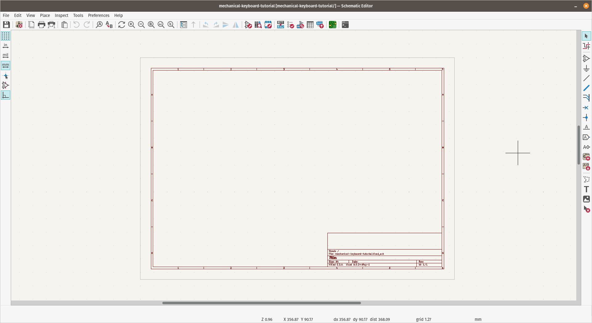
Schematic editor keyboard shortcuts:
- a - To add component.
- w - To wire components.
- v - Edit component value.
- s - Change cursor to select mode.
- Esc - Escape mode or whatever command in progress and return to normal pointer mode.
- Ctrl + z - Undo. Use liberally to undo any mistakes.
- Ctrl + s - To save. Make sure to save often!
Placing Component
ProMicro
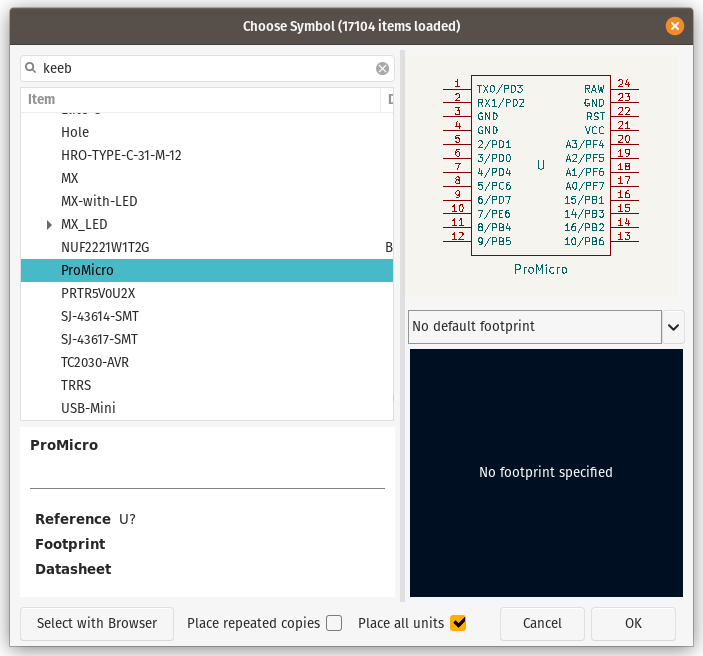
To add a component, press a and find ProMicro, this will put ProMicro schematic symbol to the sheet.
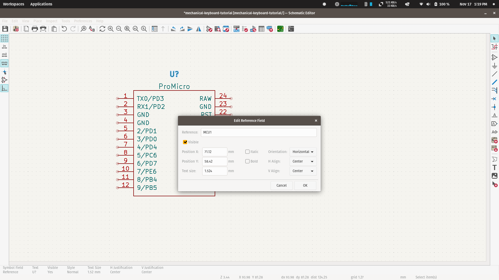
Next is to change the reference of ProMicro, to do so, click any label ended with ? and press e to change the value and change it to MCU1, or just replace the ? with 1 or any number. All reference field in schematic should end with number, like D1, SW3, etc.
Switches and Diodes
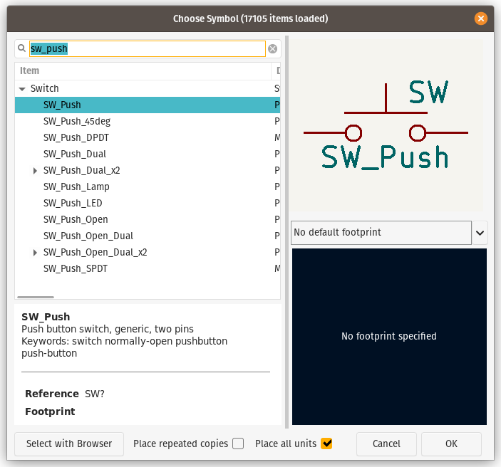
Press a again, find sw_push and add to the sheet, this will add push switch symbol that we will duplicate it later along with diode.
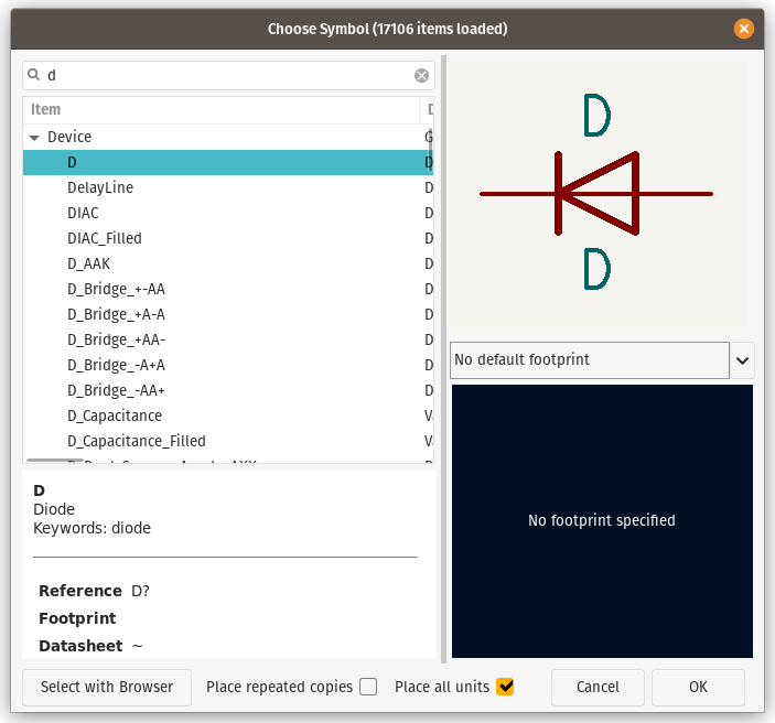
To add the diode, click anywhere on the worksheet while component placement cursor still active, and find d for Diode and place it at end of SW_PUSH end-node. Press r to rotate the symbol if needed.
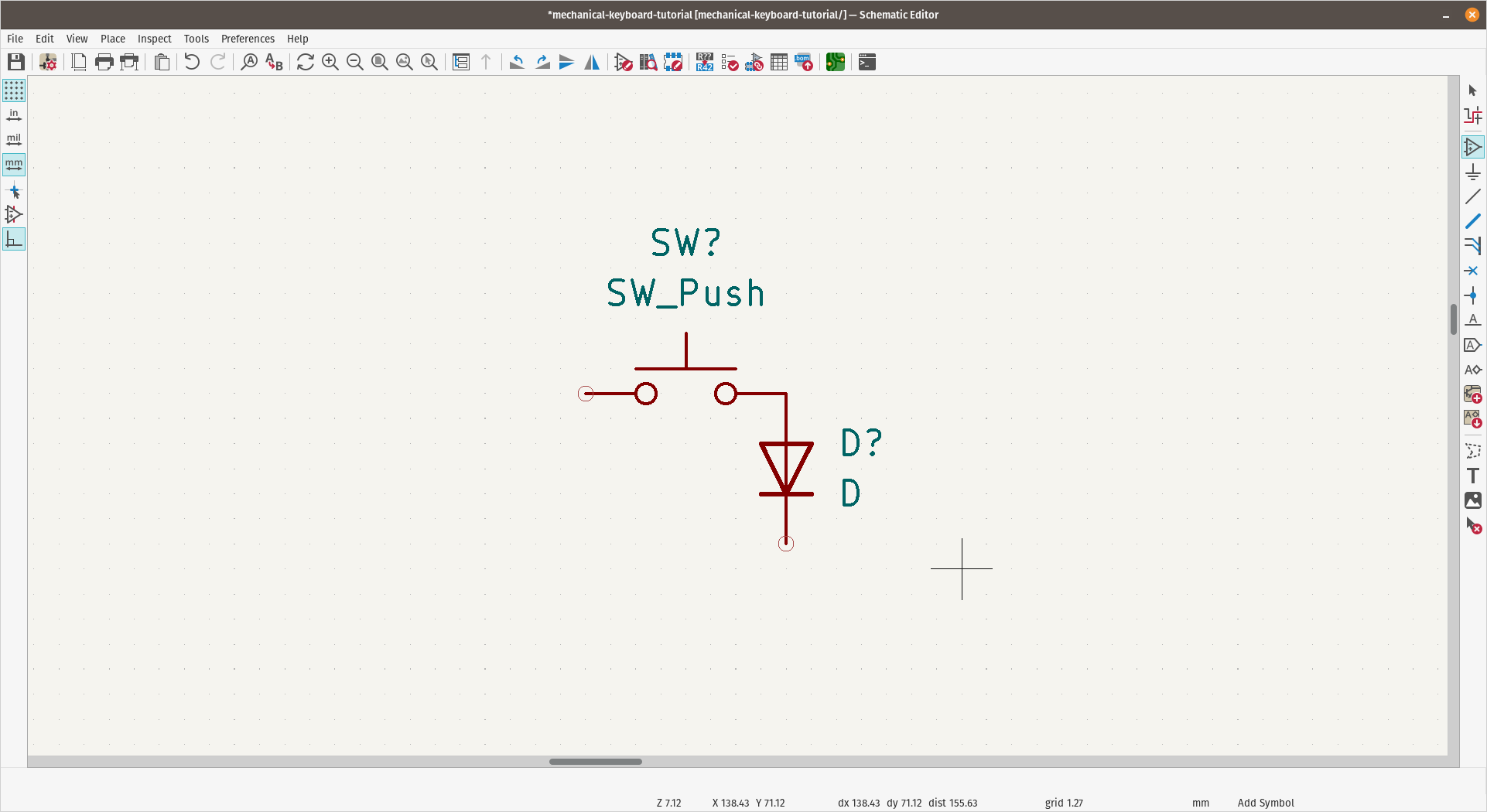
Now we will have Switch and Diode pair
Duplication
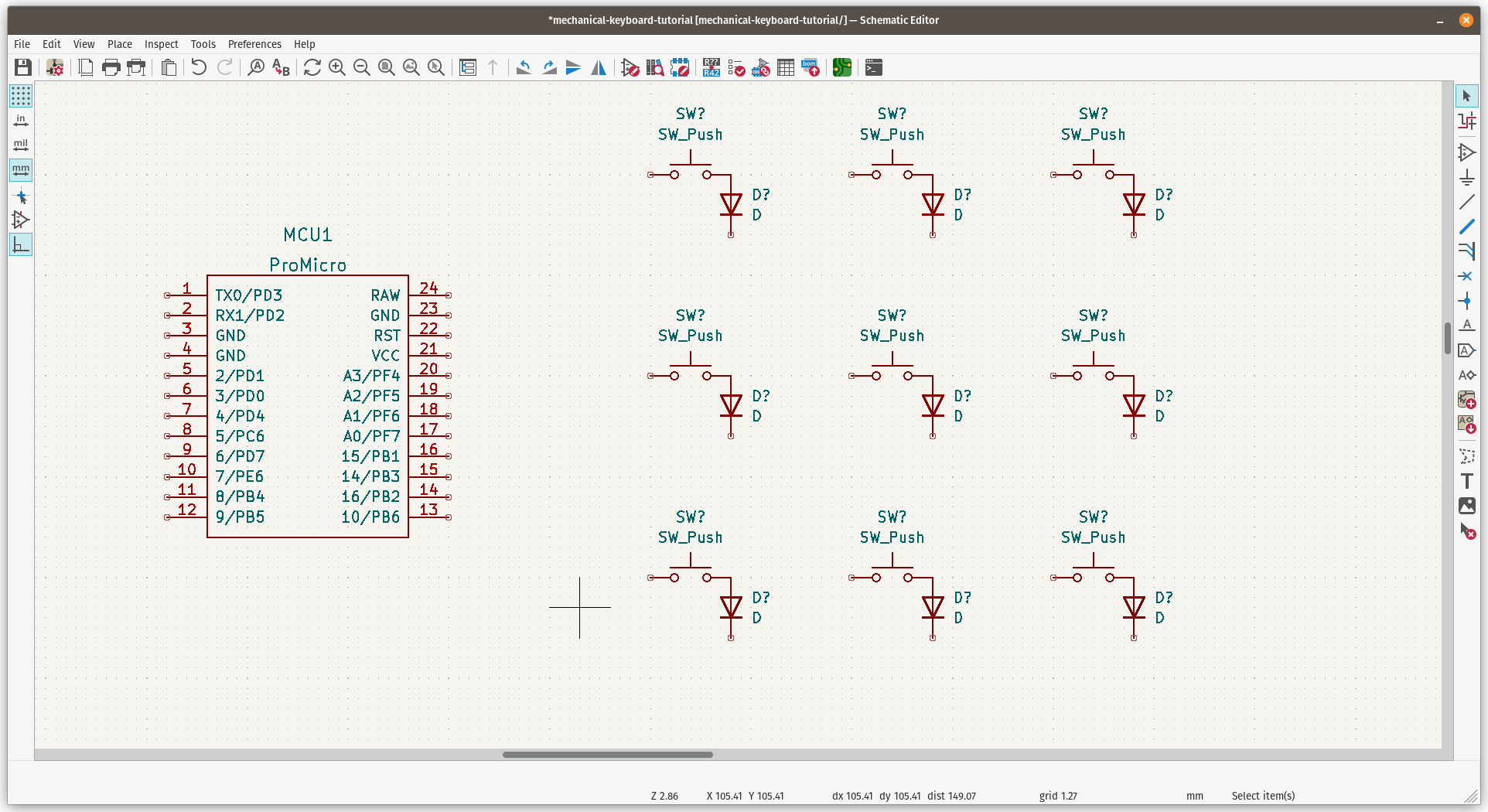
First, reset cursor by press s or Esc twice and select Switch and Diode which already in place. Press Ctrl + d to duplicate the items and place it with 3x3 grid / matrix.
Now we have MCU and 9 pairs of switches and diodes
Routing / Wiring
Hover your cursor over the start-node of the switches and draw a line to bottom and connect each of switches to create matrix column.
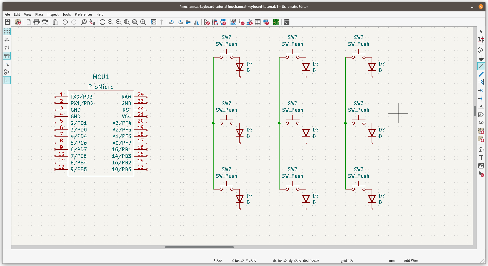
To create matrix row, just do the same but connect each end-node of diodes.
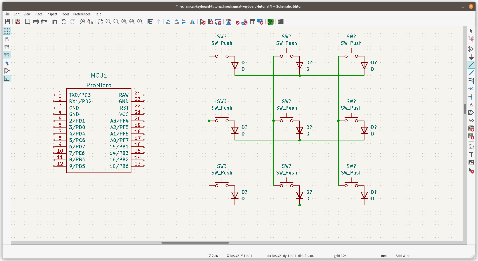
Don't bother with the switches and diodes labeling, KiCad can do it automatically later, and we have complete keyswitches matrix on schematic.
Connect MCU to Matrix
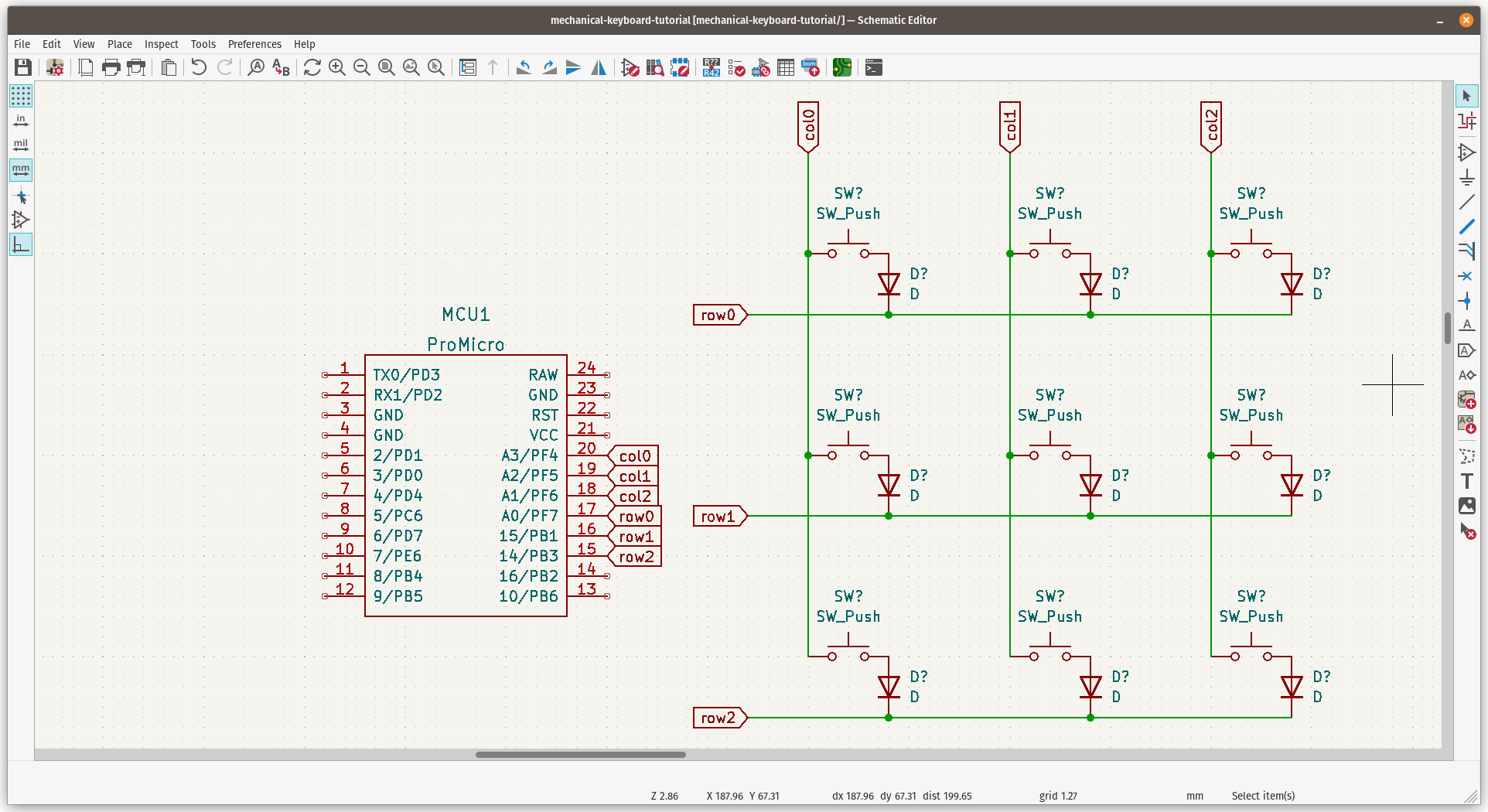
Next step is to connect the routing between ProMicro and keys matrix, we have options to use label or use wire tool to connect them, but we will go with label so we can debug or identify the rows and columns easier.
To use Label, press Ctrl + l to activate Global Label cursor. We will label it with following manner:
col0for first columncol1for second columncol2for third columnrow0for first rowrow1for second rowrow2for third row
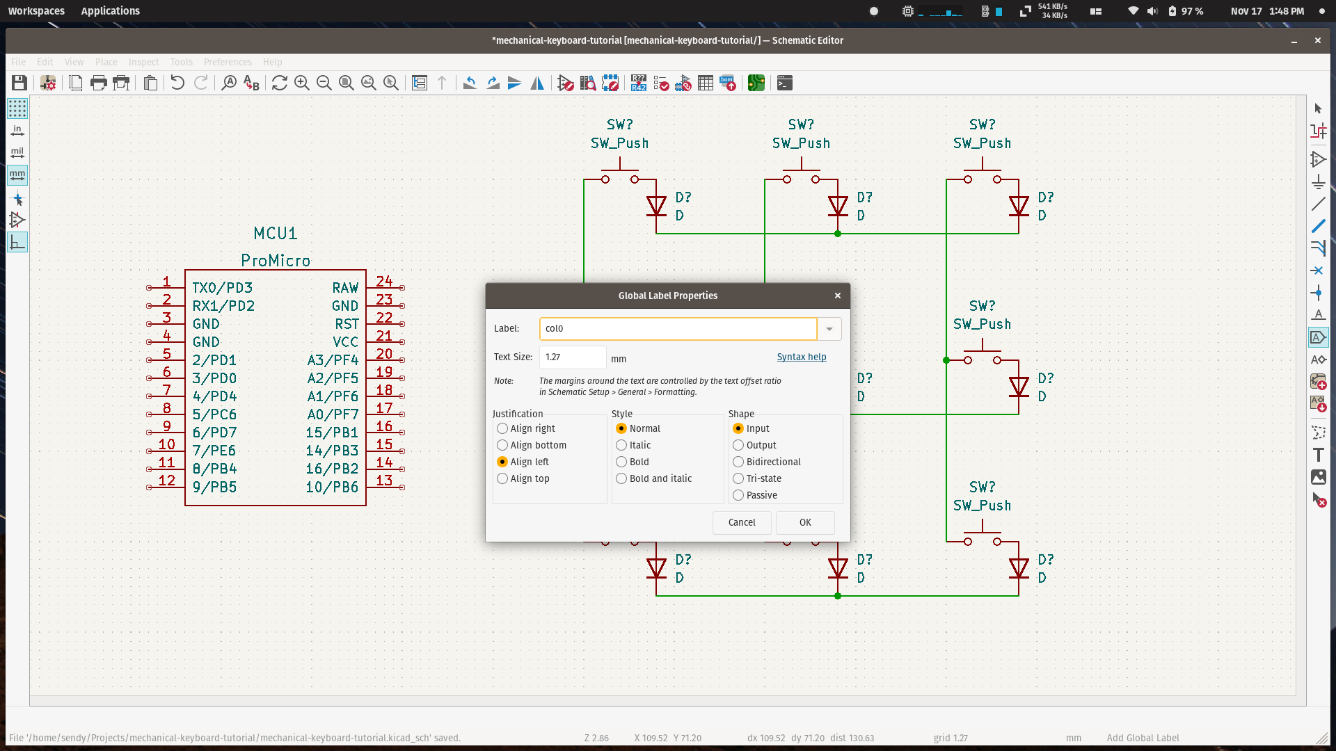
Next is to connect between MCU and matrix
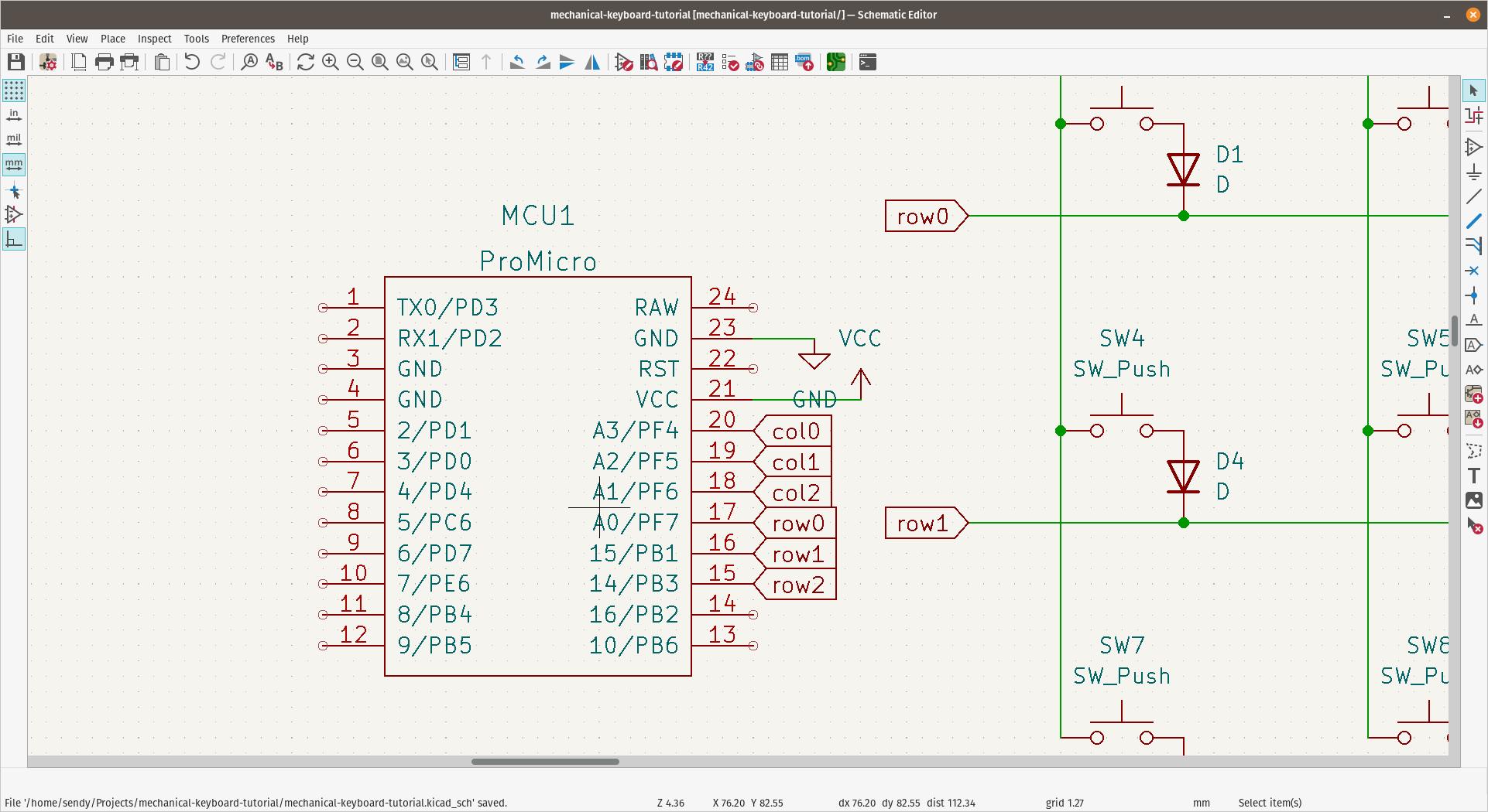
On the MCU part, press P, and connect GND symbol to GND pin in MCU, along with VCC symbol to VCC in MCU.
Assign Component
All we have done is for symbols only, they don't have any component or footprint assigned to each symbol.
On the toolbar above, click Run footprint assignment tools with this icon
If you have any component that not annotated, a window will appear to verify how you want to annotate those components, just set the config that convenient for you and press Annotate.
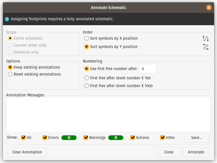
Diodes
For diodes, I will use Diodes_SMD library, and D_1206_3216 for all D symbol.
Block all the D symbol and double click on D_1206_3216 on the right tab.
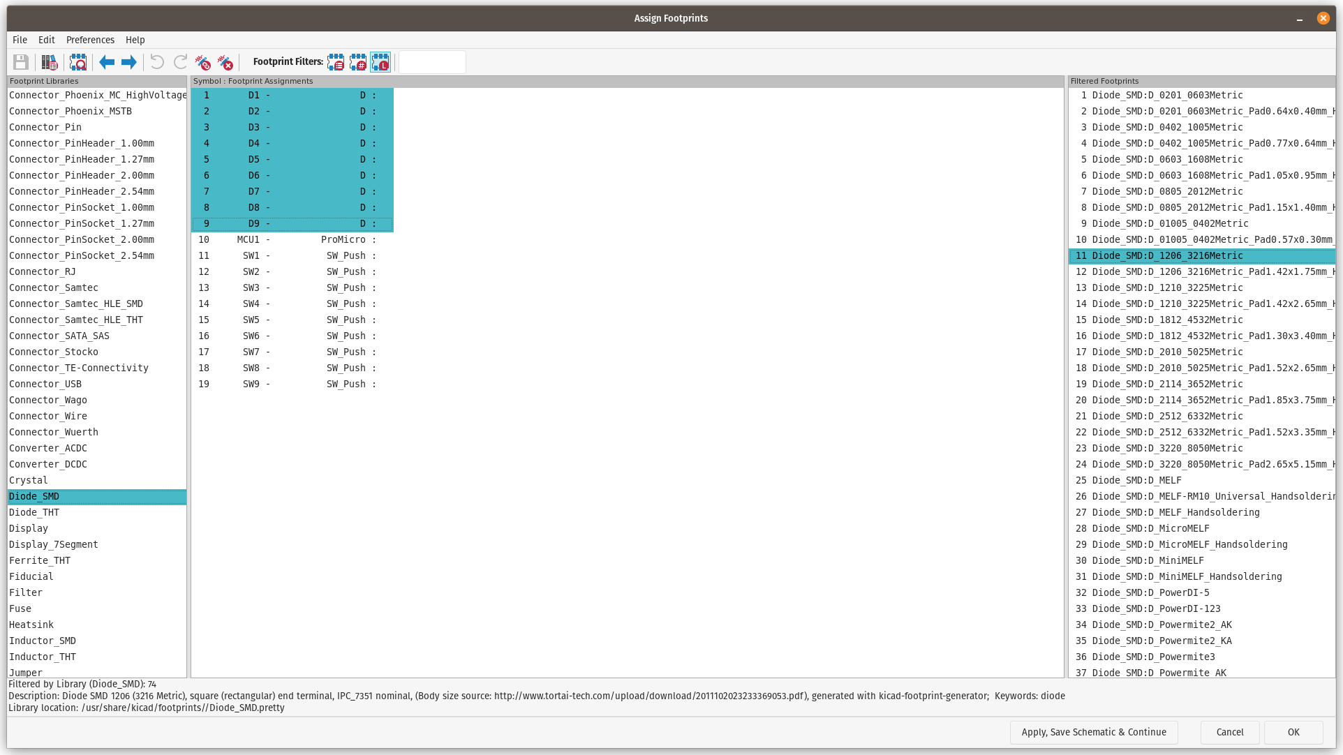
For the ProMicro, I use footprint from keebio, and the switches are MX_Only 1u.
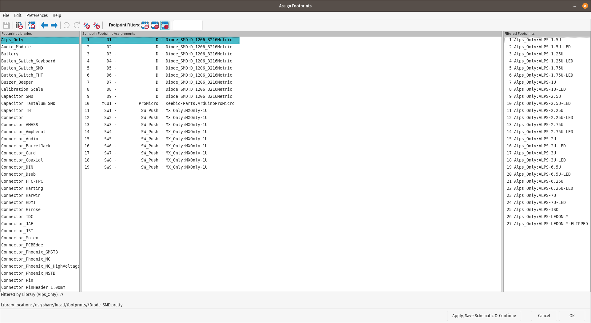
All set, and just press OK button on the dialog, next part is to set up the PCB Design.